Fan translations for Phantasy Star: Generation 1?

As part of my preliminary hacking of Phantasy Star: Generation 1, I ended up doing some searching for basic info like… how to save the game ๐Ÿ˜› (top tip – talk to the terminals in the towns using O to save your game)

Anywho, part of this saw a couple of interesting bits on possible fan translations for the game, including this one from jessethehedgehog on YouTube:

In addition, there’s also a thread on Fringes of Algo where someone as recent as April 2011 is talking about translating the game.

Not sure if either project will get anywhere, but it’s still pretty cool. Shame I don’t have the language skills or the programming ability to help out, as it would be great if G1 and G2 of the Sega Ages Phantasy Star releases received an English translation.

Mind, if Sega of America actually translated them and released them when the PS2 was a reasonably viable machine, or even in the aftermath alongside the likes of Sakura Taisen, a lot of rabid fans would have been extremely happy. If value was a problem, jam them on a disc with all the contents from the Phantasy Star Collection disc. Simple.

Well, it probably isn’t, but the internet is a choice platform for people to voice their opinions with realisation of the amount of work required to achieve such an ask ๐Ÿ™‚

Overhauling the Sega Astro City โ€“ Part 11, rewiring the cabinet

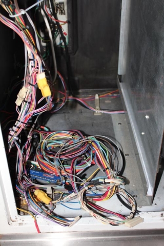
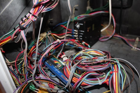
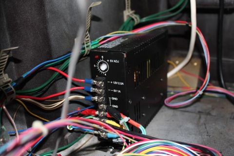
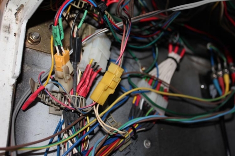
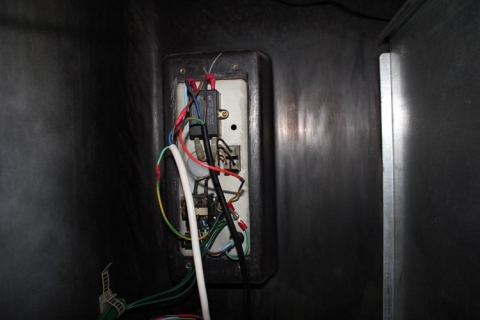
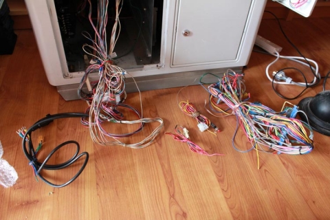
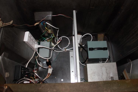
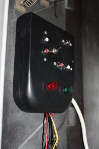
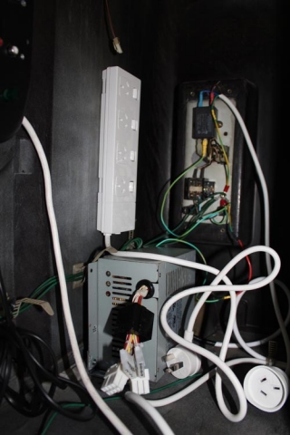
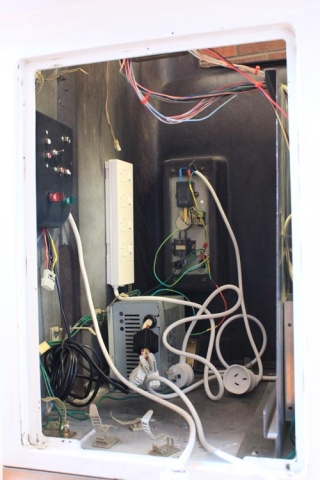
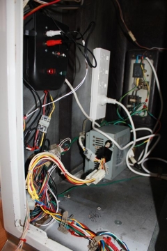
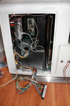
This one is best told in pictures. Let’s start with the before:

Looking inside the cabinet from the outside:

Closer up:

Power supply in focus this time:

Molex connections galore:

And the AC wiring, complete with heatshrink tubing and solder for the spliced connections:

Here’s the aftermath, with all the control panel wiring intact (since it will be reused), and all the excess wiring removed:

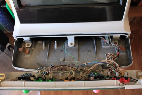
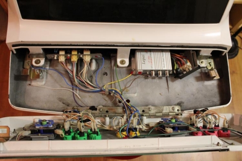
And for the sake of completeness, here’s the control panel without the bracket that houses all the molex connectors:

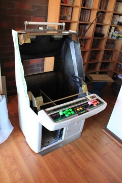
Now that all the wiring is out, next came the step of stripping everything out of the cab – the outer layers were removed that hold the bezel and speakers, exposing the fluro tube, and the monitor in its entirety (cage included) was also removed. To open up the insides for working, I also removed the partition that holds the PCB holder and separates the two halves of the cab. It really is looking like a shell now.

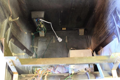
So, let’s start the refit – here’s a shot of the inside of the cab with only the new AC wiring present, with everything terminating to a female socket for ease of use:

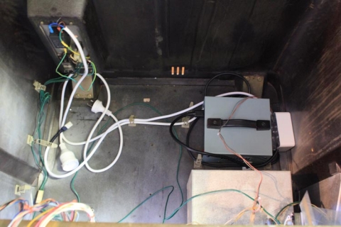
Next up, add the step-down transformer to the partition to the right:

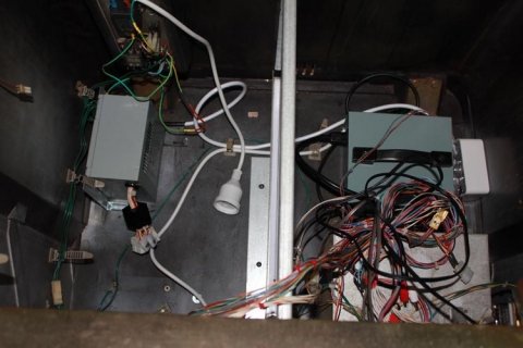
Add the partition to the cab and mount the SUN PSU into place; it’s positioned to allow for thick PCB boards, the MAME PCB or CPS2 setups, but still retain access to the unit for adjusting DC voltages:

… and another shot:

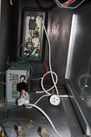
This next show shows the control box and the power board attached to the side of the cabinet:

The following closeups demonstrate when the control box and power board sit:

… and another:

… and another one:

Almost there – the JAMMA harness has been added, molex connections are complete and cable-tied close to the frame, JAMMA harness is hooked up and some RCA connections have been added for the output on the control box:

And there we go – all finished and much neater than before!

That takes care of the cabinet, but what about the control panel? We can’t forget that! Here’s a shot with the amp installed with all the wiring to the speakers and control box completed and the bracket re-installed:

And here’s the final shot with extra earth wiring grounding the monitor frame, amp, bracket and the coin slot chute/coin box:

Bit of a marathon run, but it came out really well. Next up – the new monitor!

As noted before, posts on the refurb are being done ad-hoc, so to keep track of the whole project, just use the Sega Astro City Overhaul tag, as the whole series will be added to it over time.

Experimenting with hacking Phantasy Star: Generation 1

A few years back I wrote a guide up on GameFAQs about hacking save games for Phantasy Star: Generation 2 on the Playstation 2. I decided I wanted to give Phantasy Star: Generation 1 a whirl since I finally got around to finishing it on the Master System a few years back (via the Phantasy Star Collection Sega Ages release – never finished on the SMS back in the day, it was too hard ๐Ÿ˜› Sheer tenacity and the hint book meant I could finish Phantasy Star 2 back in the day though!), but since I’m time-poor I thought I’d kick-start the grind with Alisa/Alis (choose your favourite translation :P). So, I used the experience with the previous save game hacking and applied it to PS:G1 and have had some success.

I’ll actually post up updated tutorials at a later stage for hacking PS:G2 and PS:G1 later on, but if you’re industrious you can apply the theory from my previous FAQ yourself. The only issue I’ve found is that PCSX2 0.9.7 won’t load games, but my old PCSX 0.9.4 works fine; might just be a Windows 7 x64 thing though. Had to add some C libraries to my OS as well (specifically, msvcr71.dll), as MyMC wasn’t working either. I’m using Cheat Engine v6, and it seems to be fine as well.

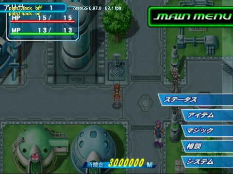
Just to prove I’m not barking, here’s my game 6 minutes or so in – note the meseta:

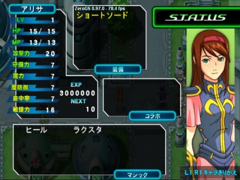
And finally, check the Experience and the Level – it’ll take me up to about level 61 after completing my first fight of the game, as that’s how the hacking works:

Anywho, just wanted to share – I’m off to play through the game properly now, not sure if I’ll hack the other characters since Alisa is such a tank now, but probably will down the road ๐Ÿ™‚ Well, I probably should since I’ll need the hex values to write up a full guide, like my previous one.

Fitting external audio jacks to a RGB to component transcoder

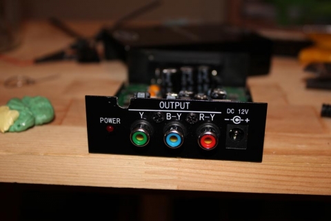
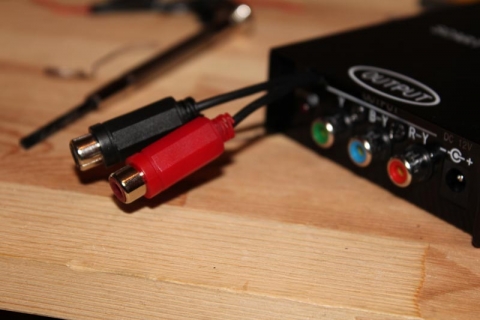
If you have an RGB to component transcoder like the CSY-2100 (useful for playing RGB retro console on a TV without SCART or RGB inputs, but happens to have component video), you may have noticed the box doesn’t have any built-in way to get audio (stereo or mono) off the SCART adapter. However, it’s not too difficult to build this on yourself if your console has no other way of outputting audio by adding a couple of RCA sockets to your transcoder. Note that in no way do I take credit for the idea – that goes to legendary modding stalwart GameSX and their equally awesome NFG forums.

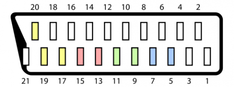
The theory is simple – consider the following from Wikipedia’s entry on the SCART standard:

Pins 2 and 6 carry right and left audio respectively, and pin 4 can act as a ground. So, all you need to do is wire something off the SCART connector inside the transcoder’s box to add an output for your audio. The following should help you achieve such a feat.

Equipment needed:

  • Two insulated wires of a length suitable for mounting the connectors – I used some old stereo RCA cables I butcher for various mods, as the shielding can be used to carry the ground to the RCA sockets
  • 2x RCA sockets (red and black in this example) you can solder to with the screw-in sleeves to protect the solder points
  • Solder, soldering iron, screw driver and drill/drill bits for threading the wires

Disclaimer

You mod your machine at your own risk. Myself nor anyone else is responsible for YOU modding YOUR RGB transcoder. If your machine doesnโ€™t work as a result of this, donโ€™t blame me โ€“ you do this mod at your own risk.

Step one:

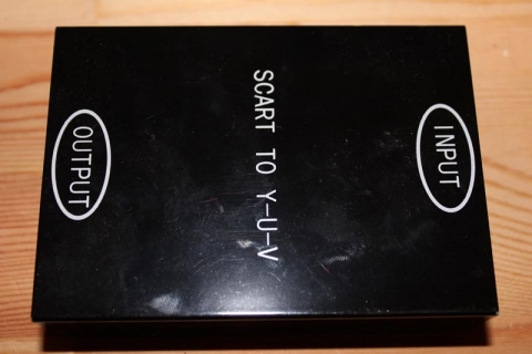
Remove the screws so this:

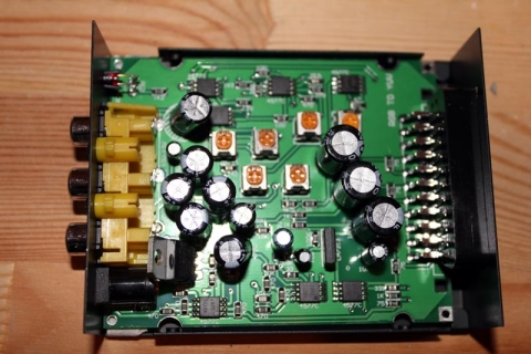
Becomes this:

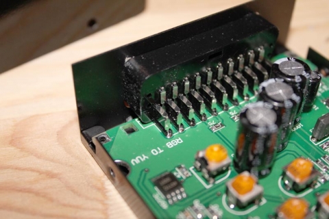
… and the part we’ll be working on is the SCART connector:

Step two:

Before we get started on the soldering, it’s time to mod the case. Since I wanted the wires to hang outside the case (there’s not enough room to mount two extra RCA sockets, though the NFG crew used a 3.5mm stereo headphone socket so that’s an option if you want to try something different), I drilled a hole on the output side of the case with enough give for two wires to hang out, and the whole is open at the top so I don’t have to thread anything through, the two wires simply sit in the groove and the top of the case will cover the top:

Step three:

Next up I cut the wires to length, stripped the ends, gathered the shielding and separated it from the signal and tinned all the tips. To make it easier at the SCART connector, I combined the shielding from both wires and tinned them together. This will make it easier to make one connection to pin 4 on the connector.

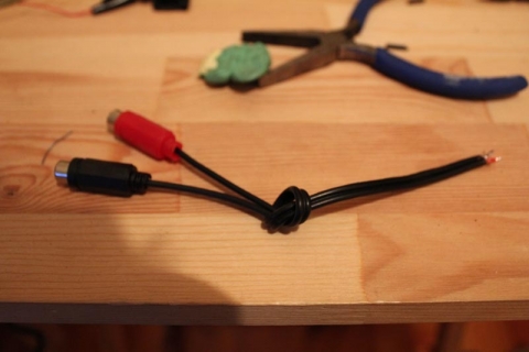
At the other end, slide the sleeves down the wires and wire up the RCA connectors. The inner portion of the shielded cable (in my case, one had red insulation, the other white) goes to the middle solder connection on the RCA socket, and the shielding goes to the outside connection. Solder everything up, test with a multimeter to ensure everything’s clean (optional, but recommended), then slide up and screw on the protective plastic sleeve.

Finally, tie a knot in the middle-ish of the cable – the idea is that the knot will hit the side of the casing before the wires tug on the soldered connections on the SCART socket if pulled, so experiment to find the best spot to tie the knot. An alternative method would be to use a cable-tie instead of a knot.

Step four:

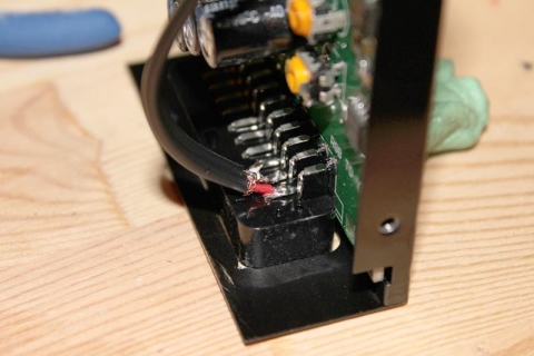
Time to solder the sucker! Using the SCART diagram, locate pins 2, 4 and 6. In my case, they were on the top row and took the first three pins from the left with the connector pins facing me. Solder Right (red) to pin 2, shielding/ground to pin 4 and Left (white or black) to pin 6. Ensure your connections are strong and clean, we don’t want any dry solder joints! Again, a multimeter makes these kind of checks simple, so I recommend you use one to test everything.

Step five:

Finally, place your wire in the area you’re ground/drilled out of the case (if your hole isn’t open on top like mine, make sure you put the wires through the hole first before soldering in the previous step), plonk on the top of the case and re-assemble everything.

And there you go – external audio-out connections to ensure you can still get sound coming from the transcoder’s box ๐Ÿ™‚

Overhauling the Sega Astro City – Part 10, mounting the MAME PC

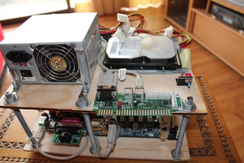
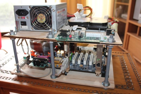
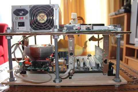
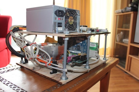
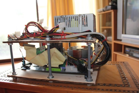
I’ve talked before (here and here) on the MAME PC I’ve worked on as part of this project – today I have some images to show how I set it up.

The aim was to have the PC mounted in a way that would easily allow me to swap it in/out of the cabinet like a PCB. To do this, I therefore needed to have it mounted on something, and due to the size of the chamber in the Astro City, I also needed to take space into account. I actually got the idea from some ghetto DIY arcade sticks I’d seen on the net, and I have to say I’m pretty happy with the end result.

It’s made up from a slab of MDF that I cut to size just slight larger than the motherboard with the mounting legs, with some extra give on the side where the accessories (graphics card, etc) stick out to allow for space for VGA adapters. The motherboard is propped up on PCB legs and screwed into the MDF to hold it in place. The top layer where the PSU, HDD and JPAC sit actually has two 80mm holes cut in a figure-8 shape that allows the CPU cooler to vent into the PSU and then have the PSU exhaust the air. To insulate the JPAC, I grabbed an old plastic VHS tape case and cut it to shape the JPAC with a rotary tool and that’s placed between the JPAC and the MDF. Small squares were then cut to act as plastic washers for the bolts so that the JPAC’s PCB wasn’t damaged when bolted down.

The poles supporting the structure were actually one long screw rod I got from the hardware store with an M10 width. Appropriate nuts and washers bind it for each layer, and I simply cut it to the necessary sizes using my angle grinder.

Everything was sized up, and bolts secure all the pieces of the setup, including cards in the motherboard, the PSU, JPAC and HDD. All the cables are secured using cable ties. The power button is routed to a DP3T switch I had lying around – simply flick it up, and it mimics the use of a power button.

All up, it works well, even if it is probably a bit rough ๐Ÿ™‚ I like it though!

As noted before, posts on the refurb are being done ad-hoc, so to keep track of the whole project, just use the Sega Astro City Overhaul tag, as the whole series will be added to it over time.