Fitting external audio jacks to a RGB to component transcoder
If you have an RGB to component transcoder like the CSY-2100 (useful for playing RGB retro console on a TV without SCART or RGB inputs, but happens to have component video), you may have noticed the box doesn’t have any built-in way to get audio (stereo or mono) off the SCART adapter. However, it’s not too difficult to build this on yourself if your console has no other way of outputting audio by adding a couple of RCA sockets to your transcoder. Note that in no way do I take credit for the idea – that goes to legendary modding stalwart GameSX and their equally awesome NFG forums.
The theory is simple – consider the following from Wikipedia’s entry on the SCART standard:

Pins 2 and 6 carry right and left audio respectively, and pin 4 can act as a ground. So, all you need to do is wire something off the SCART connector inside the transcoder’s box to add an output for your audio. The following should help you achieve such a feat.
Equipment needed:
- Two insulated wires of a length suitable for mounting the connectors – I used some old stereo RCA cables I butcher for various mods, as the shielding can be used to carry the ground to the RCA sockets
- 2x RCA sockets (red and black in this example) you can solder to with the screw-in sleeves to protect the solder points
- Solder, soldering iron, screw driver and drill/drill bits for threading the wires
Disclaimer
You mod your machine at your own risk. Myself nor anyone else is responsible for YOU modding YOUR RGB transcoder. If your machine doesn’t work as a result of this, don’t blame me – you do this mod at your own risk.
Step one:
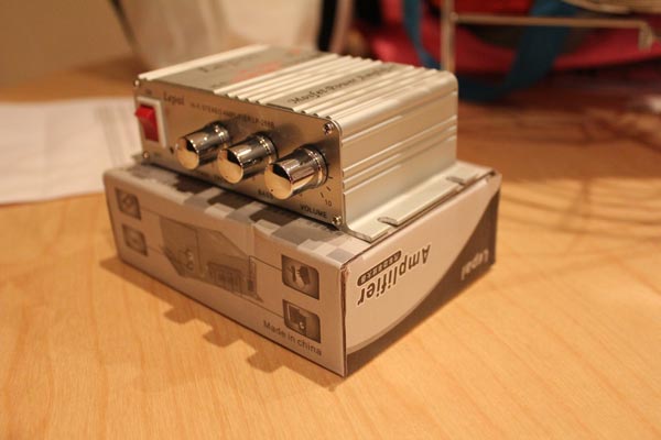
Remove the screws so this:

Becomes this:

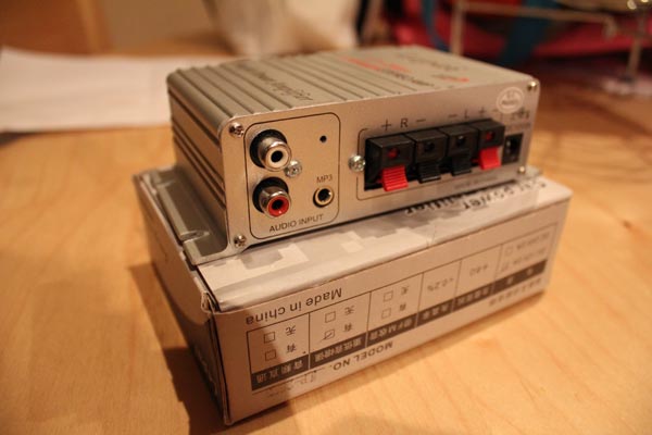
… and the part we’ll be working on is the SCART connector:

Step two:
Before we get started on the soldering, it’s time to mod the case. Since I wanted the wires to hang outside the case (there’s not enough room to mount two extra RCA sockets, though the NFG crew used a 3.5mm stereo headphone socket so that’s an option if you want to try something different), I drilled a hole on the output side of the case with enough give for two wires to hang out, and the whole is open at the top so I don’t have to thread anything through, the two wires simply sit in the groove and the top of the case will cover the top:

Step three:
Next up I cut the wires to length, stripped the ends, gathered the shielding and separated it from the signal and tinned all the tips. To make it easier at the SCART connector, I combined the shielding from both wires and tinned them together. This will make it easier to make one connection to pin 4 on the connector.
At the other end, slide the sleeves down the wires and wire up the RCA connectors. The inner portion of the shielded cable (in my case, one had red insulation, the other white) goes to the middle solder connection on the RCA socket, and the shielding goes to the outside connection. Solder everything up, test with a multimeter to ensure everything’s clean (optional, but recommended), then slide up and screw on the protective plastic sleeve.
Finally, tie a knot in the middle-ish of the cable – the idea is that the knot will hit the side of the casing before the wires tug on the soldered connections on the SCART socket if pulled, so experiment to find the best spot to tie the knot. An alternative method would be to use a cable-tie instead of a knot.

Step four:
Time to solder the sucker! Using the SCART diagram, locate pins 2, 4 and 6. In my case, they were on the top row and took the first three pins from the left with the connector pins facing me. Solder Right (red) to pin 2, shielding/ground to pin 4 and Left (white or black) to pin 6. Ensure your connections are strong and clean, we don’t want any dry solder joints! Again, a multimeter makes these kind of checks simple, so I recommend you use one to test everything.

Step five:
Finally, place your wire in the area you’re ground/drilled out of the case (if your hole isn’t open on top like mine, make sure you put the wires through the hole first before soldering in the previous step), plonk on the top of the case and re-assemble everything.

And there you go – external audio-out connections to ensure you can still get sound coming from the transcoder’s box 🙂