March is the time for console modding

In Adelaide, March is referred to as “Mad March”. Because we take a year’s worth of events, festivals and what-not, and cram it all into one month. With some exceptions. Still, it’s insanity. But that’s Adelaide.

So, to alliterate, I have decreed this month as Modding March.

Yes, that is awful. Get over it ๐Ÿ˜›

My aim this month is to try and mod as many consoles as possible to catch up on my backlog. Here’s where it’s standing at the moment:

  • Sega SC-3000H: Replace the existing cartridge connector with one in better condition.
  • Nintendo Famicom: Composite AV mod, controller 2 background hum correction, clean the cart slot and replace the membranes in both controllers.
  • Sega Master System 2: Add in a language switch and add s-video off the CXA1145 encoder using Viletim!’s simplified video amp.
  • Sega Mega Drive: Remove the existing colour mod now that I’m running a 32X and RGB in the setup, add a selectable CPU overlock switch along with the requisite halt switch.
  • Sega Saturn: Replace a dead cart slot, wire in a 50/60hz switch, then add a 3-way region switch.
  • Nintendo Gamecube: Install a modchip so I can retire my Freeloader disc and enjoy direct-boot imports. If I’m lucky it might even fix the font issues with some Japanese titles, but that might be wishful thinking! I’ve had the chips for ages, so it’s about time I sorted it out.
  • Microsoft Xbox: Remove the existing 8bg HDD and upgrade to an 80gb HDD for laziness to save me swapping discs out.
  • Microsoft Xbox 360: Repair the drive laser assembly that’s having a cry.
  • Arcade: Rewire the P4 button off the JAMMA harness so it can be patch-connected to the JAMMA+ cabling panel already in my Astro City.

I think that’s the lot. I’ve already gotten started on some of these jobs (and finished one of them last week – the SC3000H), but that’s a pretty ambitious list.

Realistically, I’m confident I’ll get the Famicom, Xbox, Gamecube and arcade mods finished as I have all the parts around. The Mega Drive shouldn’t be too tricky if the oscillator comes in the post before the end of the month (my machine’s CPU didn’t like being fed 12mhz, so I’m going to try 10mhz), same with the XB360 and getting a new drive assembly.

That then leaves a few question marks – for the Saturn, I have some replacement slots from some dead Saturns in the post, but cart slot replacements are never quick jobs (not difficult mind, just time consuming); since I’ll need to desolder and remove the dead slot on my machine, remove and desolder the working cart slot from the dead PCB, then resolder it to the working board and then add the refresh rate and language switches, that’ll take a while.

The SMS2 mods shouldn’t be hard and I’m pretty sure I have the parts lying around, so I should be able to squeeze that one in too.

So if I’m being ambitious, then the following’s my ordered list to tackle everything:

  1. Sega SC-3000H
  2. Nintendo Famicom
  3. Microsoft Xbox
  4. Sega Master System 2
  5. Nintendo Gamecube
  6. Arcade
  7. Sega Saturn
  8. Sega Mega Drive
  9. Microsoft Xbox 360

So, with all that in mind, here’s the progress breakdown:

  1. Sega SC-3000H – Completed
  2. Nintendo Famicom – In progress
  3. Microsoft Xbox – Not started
  4. Sega Master System 2 – Not started
  5. Nintendo Gamecube – Not started
  6. Arcade – Not started
  7. Sega Saturn – Not started
  8. Sega Mega Drive – In progress
  9. Microsoft Xbox 360 – Not started

I’ll update during the rest of the month as I make any progress, and since the work is likely to continue into April, I daresay there will be more updates next month too.

But the important bit was to at least get started in March ๐Ÿ™‚

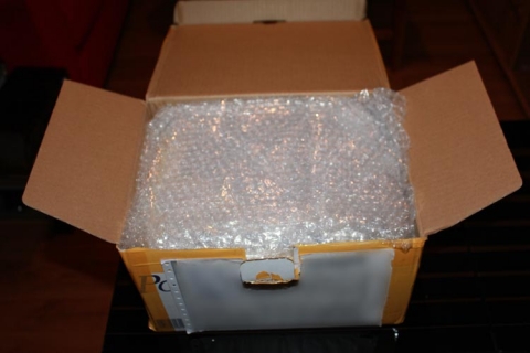
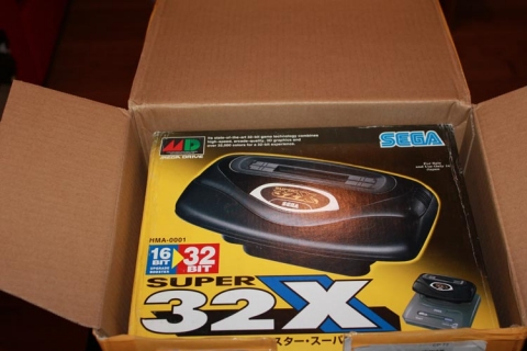
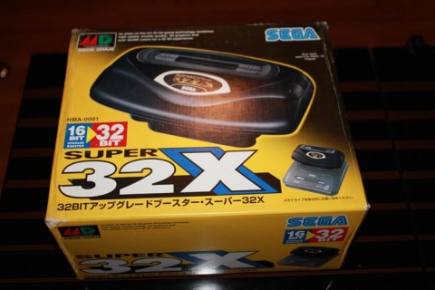
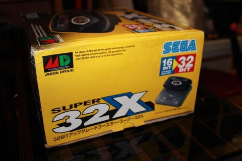
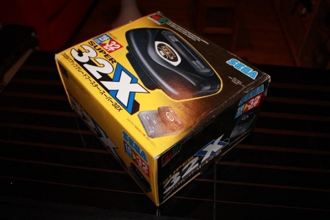
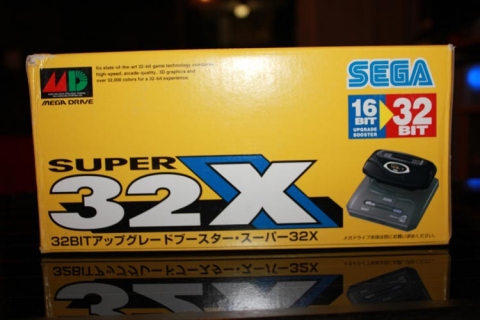
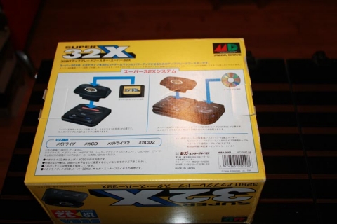
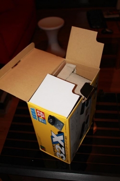
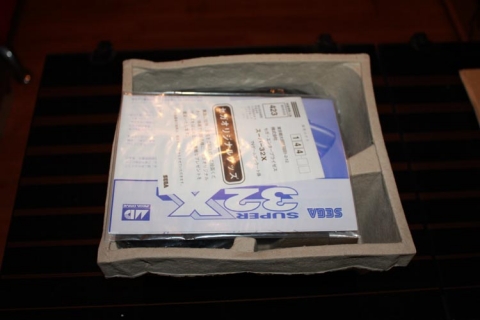
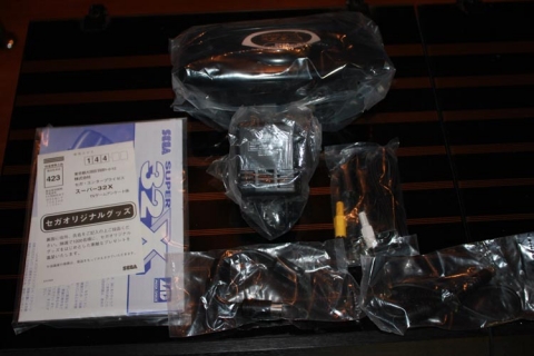
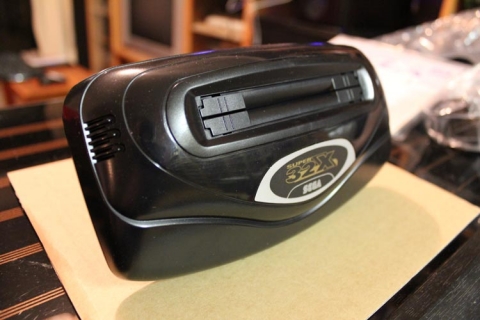
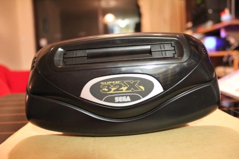
Unboxing a brand new Sega 32X!

Thanks to a tip from a fellow gamer (Hi Frank!), I have recently taken possession of a brand new Japanese 32X!!

The box was actually in very good condition given the age of the hardware, with only a few creases and dents here and there. Everything inside was brand new and complete – 32X console with the spacer (required for hooking it up to a Sega Mega Drive 2), AV-out cable, AV-in cables (including the Sega Mega Drive 1 converter cable), AC adapter (not of much use since it’s Japanese and runs on 110v) and manual. Oh, and all the original cardboard inserts, too.

As much as the 32X was much-maligned, I still have a soft spot for it. There were a handful of interesting games on the console, and back in 1994 I remember being pumped about the machine. I never ended up getting one though, as I couldn’t afford it at the time. I do remember the local Big W were clearing them out for $20 a pop in 1996, but I couldn’t get a lift from someone to get me to the nearest store in order to buy one and ended up using the money to buy something more useful. Hopefully. At that stage I would have started gaming on the SNES and was possibly starting to save for a Saturn. So, let’s assume I did something useful with that $20. I might have even used it for some gaming at Timezone Meridian. Timezone is now a shell of its former self. Here’s the Wikipedia page. It fails to mention Timezone Meridian, even though it was a building full of amazement in the 90s. Even Archive.org only goes back to 2001; would love to see some earlier archives.

Anywho, to share the love I thought I’d post an unboxing (click any of the images for a larger view with comments):

๐Ÿ™‚

Now all that’s left is to grab an AC adapter to suit, an RGB cable to hook my machine up to my transcoder and some games. Can’t wait!

Is your TV 240p compatible?

I’ve discussed before about using RGB to Component transcoders on old consoles to get the beautiful RGB video signal into something TVs with component inputs can handle. What didn’t occur to me at the time was TV compatibility.

Now, I primarily use an old 68cm CRT TV for my retro gaming, and my beloved Hitachi is kind enough to have component input (one of the main reasons I bought it back in… 2002). However, someone got in touch with me a while back saying they were having issues with playing games from the transcoder through their HD LCD TV. Turns out their set doesn’t support 240p via component, and as the transcoder outputs a 240p component signal, they were out of luck.

At first I thought it was unusual, as I hadn’t had any issues running it on my CRT TV, and our Sony Bravia HDTV (late-2007 model Bravia X) didn’t skip a beat with the unit, either. However, after looking into the issue, it seems they weren’t alone, and Samsung panels in particular seem cranky about working with 240p signals. Bummer.

So, how do you test your panel’s compatibility and what are your options? I’m no expert, but I’d suggest that if you have a Wii, change the Virtual Console to output in 240p and see what happens. Aside from that, I don’t know too many consoles that can do 240p and output component video natively. If you have a Playstation 2 and a set of component cables, you have a couple of choices:

  • Fire up one of the Sega Ages releases that contain Mega Drive or Master System games and change the display settings in-game to 240p. I know this option exists for Phantasy Star Complete Collection, Gunstar Heroes Treasure Box and Monster World Collection.
  • Load up Ico and see what happens (must be running in 60hz, the PAL version will give you the option)
  • All PSone games running out of the PS2 apparently run in 240p also (I’m assuming this only counts for NTSC games, not PAL titles), so give that a try

Props to this thread at HDTV Arcade for the latter two options, as I didn’t realise PSone titles and Ico ran at 240p, I assumed both still ran at 480i or 576i.

So, assuming your TV struggles with a 240p component video signal, what are your options? Thankfully, there are some, but I can’t take credit for that info – Tobias “Fudoh” Reich has an amazing entry on it at Deinterlacing, Scaling, Processing: Classic videogame systems on LCD and Plasma screens. His article has an amazing roundup of equipment and technical info on achieving low-res beauty on HDTVs that get cranky with 240p signals (and while you’re there, you should also read his excellent piece, Scanlines Demystified, with lots of beautiful shots of low res displays), and will hopefully point you in the right direction.

Hopefully this will help others who have encountered the same problem. Mind, none of these workarounds would be necessary if HDTV manufacturers made their devices 240p compatible, so shop around wisely, check to see if your intended purchase will support 240p via component and ask questions of the manufacturer before buying your TV.

Fitting external audio jacks to a RGB to component transcoder

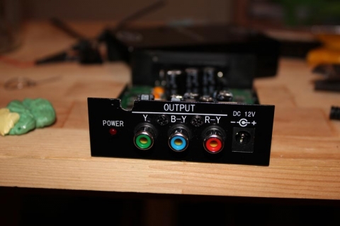
If you have an RGB to component transcoder like the CSY-2100 (useful for playing RGB retro console on a TV without SCART or RGB inputs, but happens to have component video), you may have noticed the box doesn’t have any built-in way to get audio (stereo or mono) off the SCART adapter. However, it’s not too difficult to build this on yourself if your console has no other way of outputting audio by adding a couple of RCA sockets to your transcoder. Note that in no way do I take credit for the idea – that goes to legendary modding stalwart GameSX and their equally awesome NFG forums.

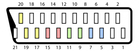
The theory is simple – consider the following from Wikipedia’s entry on the SCART standard:

Pins 2 and 6 carry right and left audio respectively, and pin 4 can act as a ground. So, all you need to do is wire something off the SCART connector inside the transcoder’s box to add an output for your audio. The following should help you achieve such a feat.

Equipment needed:

  • Two insulated wires of a length suitable for mounting the connectors – I used some old stereo RCA cables I butcher for various mods, as the shielding can be used to carry the ground to the RCA sockets
  • 2x RCA sockets (red and black in this example) you can solder to with the screw-in sleeves to protect the solder points
  • Solder, soldering iron, screw driver and drill/drill bits for threading the wires

Disclaimer

You mod your machine at your own risk. Myself nor anyone else is responsible for YOU modding YOUR RGB transcoder. If your machine doesnโ€™t work as a result of this, donโ€™t blame me โ€“ you do this mod at your own risk.

Step one:

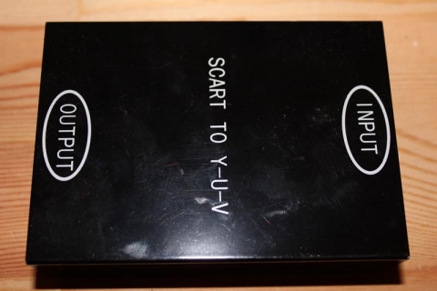
Remove the screws so this:

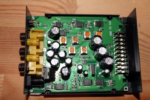
Becomes this:

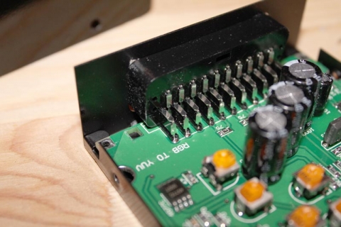
… and the part we’ll be working on is the SCART connector:

Step two:

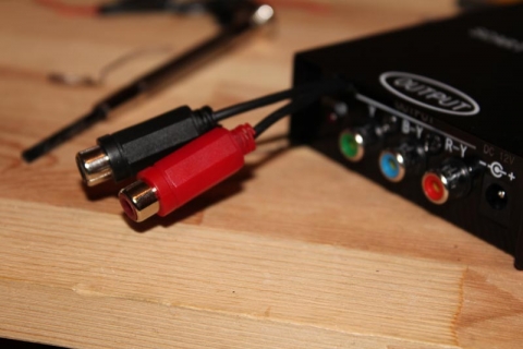
Before we get started on the soldering, it’s time to mod the case. Since I wanted the wires to hang outside the case (there’s not enough room to mount two extra RCA sockets, though the NFG crew used a 3.5mm stereo headphone socket so that’s an option if you want to try something different), I drilled a hole on the output side of the case with enough give for two wires to hang out, and the whole is open at the top so I don’t have to thread anything through, the two wires simply sit in the groove and the top of the case will cover the top:

Step three:

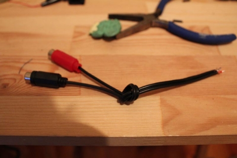
Next up I cut the wires to length, stripped the ends, gathered the shielding and separated it from the signal and tinned all the tips. To make it easier at the SCART connector, I combined the shielding from both wires and tinned them together. This will make it easier to make one connection to pin 4 on the connector.

At the other end, slide the sleeves down the wires and wire up the RCA connectors. The inner portion of the shielded cable (in my case, one had red insulation, the other white) goes to the middle solder connection on the RCA socket, and the shielding goes to the outside connection. Solder everything up, test with a multimeter to ensure everything’s clean (optional, but recommended), then slide up and screw on the protective plastic sleeve.

Finally, tie a knot in the middle-ish of the cable – the idea is that the knot will hit the side of the casing before the wires tug on the soldered connections on the SCART socket if pulled, so experiment to find the best spot to tie the knot. An alternative method would be to use a cable-tie instead of a knot.

Step four:

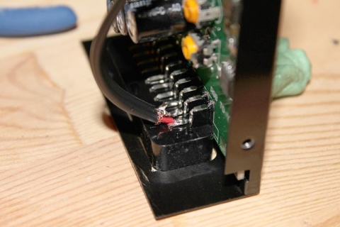
Time to solder the sucker! Using the SCART diagram, locate pins 2, 4 and 6. In my case, they were on the top row and took the first three pins from the left with the connector pins facing me. Solder Right (red) to pin 2, shielding/ground to pin 4 and Left (white or black) to pin 6. Ensure your connections are strong and clean, we don’t want any dry solder joints! Again, a multimeter makes these kind of checks simple, so I recommend you use one to test everything.

Step five:

Finally, place your wire in the area you’re ground/drilled out of the case (if your hole isn’t open on top like mine, make sure you put the wires through the hole first before soldering in the previous step), plonk on the top of the case and re-assemble everything.

And there you go – external audio-out connections to ensure you can still get sound coming from the transcoder’s box ๐Ÿ™‚

I picked up a PC Engine Duo-R :)

Last year I became a member of the nerdy PC Engine fanboy community with the purchase of a PC Engine Duo-R pre-modded with RGB for super-awesome video output ๐Ÿ˜€

Admittedly it’s a bit late, but here are some pics to enjoy!

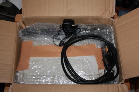
Unboxing the Duo-R:

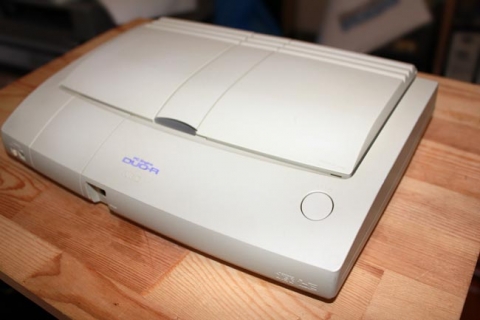
Angled shot:

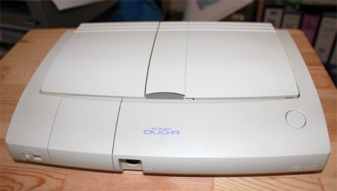
Front shot:

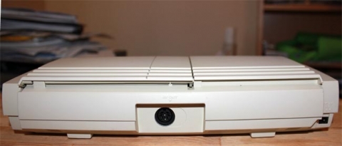
Rear shot:

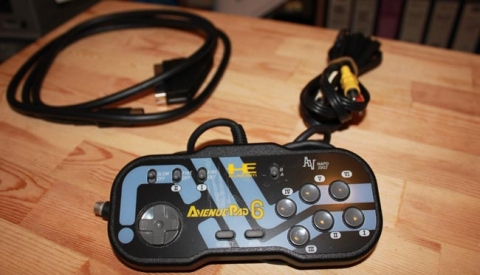
NEC Avenue Pad 6 and cables:

All these and more images are up in the PC Engine gallery.