Modding March update!

modding-march-2012-consoles

Okay, here’s the latest update on my modding to-do list:

  1. Sega SC-3000H – Completed
  2. Nintendo Famicom – Completed
  3. Microsoft Xbox – Completed
  4. Sega Master System 2 – Completed
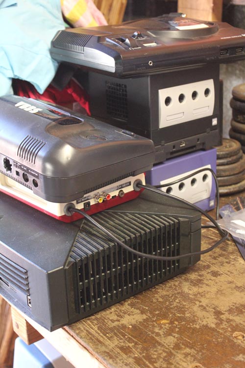
  5. Nintendo Gamecube – Completed
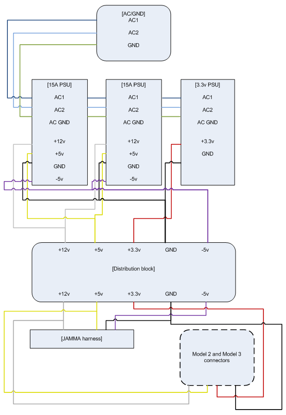
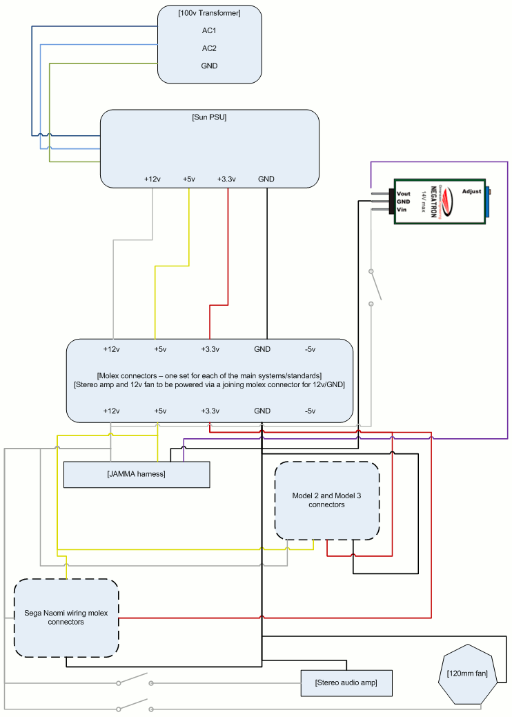
  6. Arcade – Not started
  7. Sega Saturn – In progress
  8. Sega Mega Drive – In progress
  9. Microsoft Xbox 360 – Not started

Not bad, huh? Since a few things changed up with the modding, I thought I’d give a quick rundown of what happened:

Sega SC-3000H

modding-march-2012-sc3000h
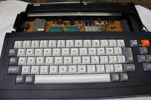
This one was time-consuming rather than difficult. The only drama I had was where one of the pads came away from the PCB when desoldering the old connector, but that was easy to fix by wiring the new cart connector directly back to the trace.

Nintendo Famicom

modding-march-2012-fami
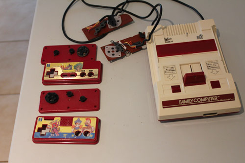
Composite AV mod came off nicely, the controller hum was also an easy fix and the controllers have come up nicely after being disassembled and cleaning the contacts and replacing the membranes (NES membranes fit the Famicom without any dramas). Since the controllers had some charming (but disheveled – see the image above) Dragon Quest sticks on them, I soaked the plastic shells in warm soapy water for a few hours and gave them a gentle scrubbing in some fresh hot soapy water and the stickers, along with their residue, came off nicely.

Sega Master System 2

modding-march-2012-sms2
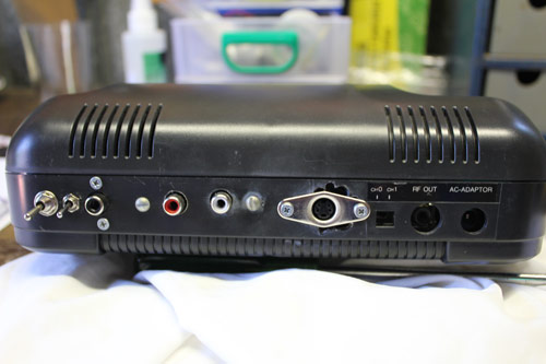
I was working on my original Master System 2 I picked up well over ten years ago when I started getting into retro gaming again. As a result, it was also one of my early mods… actually, I think it was my third one – the Saturn was my first (50/60hz switch, 1999), followed by an unsuccessful SMD1 (language/refresh rate switches, 2000). My SMS2 mod was originally just a 50/60hz switch, then I got a bit more daring and added composite video/mono audio. After that, I decided to add another RCA socket and rewired it for dual-mono out (saved having to add a RCA splitter on the audio socket), and attempted to add a language switch but couldn’t get a clean cut on the IC leg that needs to be modded; these were all done in 2000, with the language switch mod being done ~2001. I also attempted to add s-video to the SMS2, but between butchering the back of the machine to fit the socket (that wouldn’t fit because the hole was hodge-podge and too big – see the image for the unfortunate result even after adding a new s-video socket!) and not having s-video on my TV, I left it at that. Looking at my past work was a little embarrassing, but at the same time it was also heartening as it’s demonstrated how much better I am with a soldering iron now compared to back then. Mind, it also helps that I have better equipment now!

So, as far as the new new mods went, it came off nicely – the simplified s-video mod by Viletim! looked great, with no jailbars visible on my TV (for reference, I used 27ohm resistors, as recommended by fellow modder Mamejay).

I also added the language switch, which proved a bit tricky as my anal-retentivity suggested I didn’t want to leave the leg on the IC floating, so I wired it up to go between +5v and GND off the voltage regulator. When this didn’t make a difference to the games I tested, I went back and thought the error was being caused by the leg on the IC itself, as my butchering of the leg in 2001 actually broke it off at the IC so the solder didn’t have much to hold onto. So out came the rotary tool and I gently ground back the IC around the leg to get started, then manually scraped a bit more away around the leg with one of my precision flat-bladed screwdrivers to get more of the IC leg visible and thus available for soldering. After getting a very solid connection, I went and tested again, and still no luck.

At this stage I was getting a bit angry, so I went and read up a bit on SMSPower, and realised everyone was saying to let the leg float – the tute I was working off just said to temporarily ground the leg, and I just assumed this meant the leg was otherwise getting +5v from the PCB; turns out if I flipped the PCB over and traced the path with my multimeter, I would have found that the leg is normally left floating when in English mode. So, I went and disconnected the +5v line, went back and tested it and voila, it’s working!

Sega Mega Drive

modding-march-2012-smd1
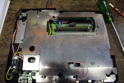
I said in last week’s post that I removed the old oscillator, added in a 12mhz one and had system stability errors. Since I know it’s important to keep clock lines short, I figured I’d jump in and reposition the oscillator by having it close to the switch/CPU and thus create a shorter line of the clock to travel along; I also added thicker-gauge wires to take the +5v/GND from the voltage regulators to ensure the oscillator was fed a good power supply. You can see the “before” picture of where I positioned the oscillator, which is next to the headphone socket. Unfortunately it didn’t make much difference, but I don’t consider it as a wasted exercise, as it’s best-practice to keep the lines as short as possible. Since the oscillator is on a bit of perfboard, it will be easy to desolder the existing component and add a 10mhz oscillator I have on the way. Should only be a 30-minute job, if that – I’m not the fastest at soldering/modding, but at least these days I’m more thorough ๐Ÿ˜‰

Sega Saturn

modding-march-2012-saturn
The replacement cart slots are in the post, but I did succeed in adding a 3-way region switch and 50/60hz mod, which is a bit of an achievement for me as I haven’t had much success with the three-way switches in the past. Admittedly the last time I tried doing one of them was back in 2002 or 2003 and in a time where I had less experience and poor tools in comparison to what I have now. I’m very happy with the result, despite the unusual board design (it’s a very early model PAL PCB, with the JPs spread across both sides of the board). I was also able to use the veroboard to provide the +5v/GND for the 50/60hz switch, which helped make things clean. I’ve noticed the power supply on it might be on the way out owing to the rolling bars and CD-ROM issues that hit after an hour or so of testing, so I’ll either look at swapping it with another supply that gives the correct voltages (GND/GND/+3.3v/+5v/+9v) or replacing the caps to see if that helps.

Nintendo Gamecube

modding-march-2012-gcns
I ended up wiring the XenoGC chip to the drive assembly rather than soldering it directly to the PCB. Took a little extra time, but it made it much easier to double-check the solder points with the multimeter and avoid accidental solder-spillage onto adjoining pads.

While I had the GCNs disassembled, I gave the outer cases a wash and I also modded my purple Cube to have a shiny blue LED instead of the standard orange one – blue LEDs are fun ๐Ÿ™‚

The machines successfully loaded PAL and US games directly, so I’m really happy with the result ๐Ÿ˜€

Microsoft Xbox

This one was an easy job, but was time consuming to get it setup in the way I wanted. It was also the first time using the Slayers disc to take care of everything (the machine was already chipped), so I didn’t have to worry about popping off the doors to my PC to run the usual HDD tools to prep a machine and found it ran nicely. With everything now configured (including adding the video.bin 0-byte file to the HDD to force UnleashX to run in 480i over component), I’m very happy with the machine. Now I need to sort out a save file for Dead or Alive Ultimate with everything unlocked because I’m lazy ๐Ÿ˜‰

For those curious, I took photos of most of the mods I have done thus far and intend to write up tutes on them at some stage down the track, along with plenty of others I have in the wings.

Anywho, all that’s left now is the SMD1 overclock (oscillator to arrive soon I hope), XB360 DVD fix (need to get a laser assembly sorted) and arcade button wiring. If the oscillator comes in time, I’d say the SMD1 should be sorted this month; the arcade fix is pretty easy as well and should also make it. If the laser assembly for the XB360 comes in this month, I’ll get that sorted as well; can’t see this one happening though, so it might be a job for April.

Getting Virtua Fighter 3 running in my Astro City

This one’s very retrospective, as I did this back in… late 2009 I think, or early 2010. It’s a response to the issues I’ve blogged previously with getting VF2 and VF3 to run on my cabinet.

I grabbed an AT PSU with some hacked wiring to a DIY power distribution panel. It was crude, but very effective – with some jiggling around and by using the power supply/connections in conjunction with a Model 3 – JAMMA harness I had from a previous order, I was able to get VF3 running on my cab ๐Ÿ˜€ Made me a very happy little nerd, I can assure you!

Angled shot of everything:

Power supply:

Squeezing everything inside the cabinet:

Success!!

The whole lot (and then some) are in the Arcade stuff – cabinets gallery.

Overhauling the Sega Astro City – Part 5, roundup

Continuing on from part 4 of this series, let’s move on to part 5 – a short summary!

With all the groundwork done, I’ve whipped up a short summary noting my “to-get” list:

Item Comments Price
Terminal block 2x 12-way 30A blocks, dividable $5.70
3m AC cabling For new AC wiring $7.50
General purpose hook up wiring Better quality wiring for general purpose stuff $4.95
New JAMMA adapter Replace existing, tired JAMMA cabling $19.95
Naomi Molex adapters for: (a) male Model 2/3 adapter, (b) male JAMMA, (c) male and female for 12v/GND lines for accessories Naomi molex plugs included with PSU; if can’t get female Naomi molex plugs, run an extra 12v and GND run from each adaptor to a more generic molex, and use that to hook up to a molex off the 12v patch bay $15.00
Molex adapters for chassis and fluro To be determined $15.00
2 x red SPST 12v switch Used to power fan/negatron $7.90
1 x green SPST 12v switch Used to power audio $3.95
1 x 3PDT switch Audio source switch $7.95
2 x 120mm fan guards For protecting against injury on 12v fan $9.90
Negatron Used to obtain -5v on the JAMMA harness $25.00
Stereo audio volume controller Fit to outside to replace current controller, runs off final volume output $21.95

That’s my theoretical list with pricing, which may or may not change over time – these posts are a little retrospective, so more updates will come as they happen. Note that this list doesn’t cover the big purchases, which are the Sun PSU and the chassis from Jomac, this is more the ancillary goods to help get everything together.

Once everything’s been gathered and finalised, I’ll then prepare a project timeline noting what needs to be done in the correct order to remove the old components, fit the new ones, test, and finalise the project. We can only hope there isn’t too much scope creep ๐Ÿ™‚

So that’s part 5 โ€“ part 6 and onwards will be ad-hoc updates, so to keep track of the whole project, just use the Sega Astro City Overhaul tag, as the whole series will be added to it over time.

Overhauling the Sega Astro City – Part 1, power supplies

I’ve been meaning to write something up on this long-winded project for a while now, so here I go – not sure how many parts there’ll be to this job, so we’ll just have to wait and see ๐Ÿ™‚

I’ve recently been looking at the existing setup inside my Astro, and can’t help but feel that it needs some work. The wiring is a bit of a rat’s next at times, I don’t know where all the cabling’s going, I’ve had to beef up to wiring on the 5v connections to increase the PSU’s output, the PSU itself is on the way out, as is the existing arcade monitor.

Where things got to a bit of a head was with regards to power issues – I’ve recently grabbed a Naomi and currently have a couple of Model 2 and Model 3 boards that need a reasonable amount of juice on tap. So, I figured that maybe I should investigate rewiring the way the power supply worked. The problem here was finding a power supply that couple happily take everything from a mid-80s PCB all the way through to resource-hungry Model 3 and Naomi setups. This left me with two options:

Option 1 – Parallel PSUs

Parallel 3 PSU wiring

In this case, I’m taking the 240v AC supply, chaining it across my existing 15A arcade PSU, chaining it to another 15A PSU and finally chaining it to a 3.3v PSU I bought a while back. From here, I then wire it to a distribution block, which connect to suit Naomi, Model 2/3 or JAMMA.

The pros with this is that all I need is another PSU (cheap and accessible), it runs off 240v (no need to run it through the transformer), and doesn’t require too much tomfoolery.

However, against this is – will it actually work on games that need a full load? What if one fails? Is it really safe to be mixing too PSUs together to get this kind of power distribution.

This then leads to option 2:

Option 2 – Dedicated PSU

Sega SUN PSU wiring, original plan

In this case, the aim is to grab a Sega Sun power supply, since they are great pieces of kit and are certified to power anything you can throw at them.

There are some challenges with this – cost (they’re more expensive and more difficult to get locally), only 110v (therefore would require some extra work on hooking it into the transformer), no -5v output.

In the end though, I decided to go for the above setup – fork out the extra for the PSU, grab a Negatron to introduce a true -5v connection where necessary for older boards, and run them all off a distribution block.

However, after chatting with some more experienced arcade builders, I decided to change the model a little – instead of having a big distribution block, I decided to simply create a handful of male JST plugs for each connection (e.g. JAMMA, Model 2/3 and use standard cabling for the Naomi) and hook them directly into the JST power plugs on the PSU. The following is the final run:

Sega SUN PSU wiring, take 2

So, I figured if I was going to start rewiring some areas of the cabinet to accomodate the PSU and make the whole setup more universal, there are two other factors to consider – amplification for line-level sources and getting the 12v fan from the Model 3 setup up and running when needed – you’ll see these (as well as switches to accomodate them and the Negatron when needed) have been added to the above diagram.

But I’ll stop here before I get too carried away – part 2 will deal with more of the planning behind this project.

To keep track of the whole project, just use the Sega Astro City Overhaul tag – the whole series will be added to it over time.

Update on power supply problems with Virtua Fighter 3 (Model 3) PCB

Finally have an update on the power supply problems I’ve been having with my Virtua Fighter 2 and Virtua Fighter 3 respective Model 2A and Model 3 boards.

After tracking down an eBay sale of a Model 3-fitted and ready PSU, I buckled, bought it, and it finally arrived yesterday. I gave it a preliminary run to see if I could get the thing to power up, and it looks like we may just be in business ๐Ÿ™‚

The setup’s nothing too refined, but is startlingly effective – it’s basically a standard ATX power supply running on 240v with the 12v, +5v, +3.3v and GND going to a couple of distributors on a block of wood, and the distributors rope around to the various connectors on the board. The input and video run back to a JAMMA biscuit, and the sound (not connected) has been wired to a 4-pin molex connector, but currently doesn’t have an amp fitted.

Moving forward, from here I’ll need to take the Wei Ya audio amp off the existing Model 3 >> JAMMA adapter I have and fit that into the loop and connect it up to the JAMMA biscuit to get sound going through. Will have to look at doing something similar for my Model 2 board as well, might see if there’s a way I can quickly hook up the PSU to my Model 2A filterboard to at least test the thing and see if I can get the sucker powering up.

The funny thing with all this is that Wifey said ages ago that I should have gone out and grabbed a big beefy power supply for the system before messing around with everything else I’ve done. Looks like she was right all along ๐Ÿ™‚

Once I’ve had a chance to properly connect the whole shebang together and get it up and running, I’ll post up some pics to share. Might also prove useful to other people interested in doing similar mods on their systems.