PAL Sega Mega Drive colour correction – 60hz in full colour in RF, composite and S-Video!
Update (7 April, 2011): I’ve noticed this method introduces noise in the RGB channels when playing games via RGB or via a transcoder. Therefore I recommend you add a switch to go between the original signal and the oscillator for best results. A tutorial to do this can be found here.
A few years back, with the help of the regulars at the NFG forums/GameSX (in particular, Viletim! was instrumental in helping me with this), I was able to put together a relatively simple method for getting 60hz in full colour out of a PAL Mega Drive when output via RF, composite and S-Video, and a method that still kept the full colour signal even if switched back to 50hz on the fly. Apologies in advance for some of the pics, but I hope other modders find this one useful. The other essential resource for getting this happening was Charles McDonald’s Home Page, so huge thanks out there as well.
Equipment needed:
- 4.43mhz crystal oscillator (WES Component # QXO-1100, source [Australia])
- Thin-gauge wire
- Soldering iron (15 or 25 watt – I use the latter, but 15w ones are better I’m told)
- Solder and desoldering wick (if you stuff up)
- Stanley knife or something sharp to cut PCB traces
- Screwdriver (d’uh!)
Disclaimer
You mod your machine at your own risk. Myself nor anyone else is responsible for YOU modding YOUR Mega Drive/Genesis. If your machine doesn’t work as a result of this, don’t blame me – you do this mod at your own risk.
Intro
Throwing a 50/60hz switch is easy to do on a Mega Drive – for PAL gamers, the problem is to get it to output the 60hz signal in colour. Providing you have a telly that can accept RGB via SCART, this is a non-issue – the RGB feed comes out great regardless of whether its in 50hz or 60hz. Should you have a 32X, you’re also set – the a/v-out on the 32X cleans up the 60hz colour issue, though apparently some early model Mega Drives still have issues despite this.
So, if like myself and plenty of others you don’t have a SCART socket on your telly or a 32X, this mod will show you how to fix up this arse of a fault in your PAL Mega Drive and get it to output 60hz as a proper PAL60 signal, whether it be via crappy composite leads or a custom-built s-video connection. Props out to viletim! from the NFG Games forums who came up with the solution btw – we in the community owe this one to him! Note this was all done on an original model PAL Mega Drive, not model 2 or 3 or what-not; your console may differ from mine, so you mod your machine at your own peril.
Step one: Disassemble Mega Drive
This one’s pretty easy so I won’t go into it – disassemble the whole lot, including the heatsink and everything. We want to be able to take the PCB (printed circuit board, or the board that is the guts of the Mega Drive) entirely out off the case to get to the underside of the PCB itself. If you know your way around the Mega Drive, you could probably skip taking the heatsink off the board itself if you know where the CXA-1145 chip is; otherwise, remove it.
Step two: locating the chip
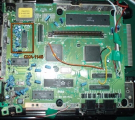
The aim of this mod is to feed a new signal onto pin 6 of the Mega Drive’s CXA-1145 chip to get it to generate a colour picture when it’s running in 60hz. Obviously to do this we’ll need to find the chip. The CXA-1145 (or the Irony Chip as I call it – “It’s a Sony”) is located on the top left-hand side of the PCB underneath the poxy RF mod we all used in the 90s owing to our crap-tacular tellies. See the image below for a general guide:
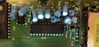
Or for a dodgy close-up view, here’s this:
Our victim will be pin 6 of the CXA-1145, which is the oscillator input. Apparently anyway. Viletim! said it was, and my crap understanding of schematics reckons that’s what its called, so we’ll call it that. You could also name the pin the “Mr Bob” pin or “I wish I were as cool as Sauceman” pin for all I care (“Kloppy is a champ” pin is another), as long as you use pin 6, it’s all good. To work out which is pin 6, count from the bottom-right of the chip if you’re looking at it normally, or in the above image, the bottom left-hand side (the one with a little ‘1’ printed on the PCB) and count up six pins… or just use the above image as a guide and count to the right. It’s all good.
Step three: Cutting the trace
Now we’ve located the chip and the pin, we need to turn the board over so we can attack it with a stanley knife or equivalent cutting device (I’ve heard of x-acto knives or somesort being talked about in the past – whatever, as long as you can use it to cut a trace on the PCB). You could use pin 1 as a guide and count up then follow the traces from pin 6 through a capacitor and a resistor to get to the point we need, but thanks to the power of the intarweb [sic] and some schematics available online, we can use the references to the capacitors and resistors to work out what we’re supposed to cut.
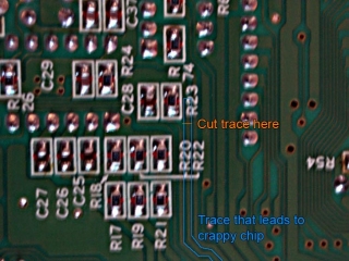
You’ll need to look for ‘C28’ and ‘R23’ – see below:
Now, the astute observer will notice that there is a thin trace that runs off the resistor and continues along its merry path to the 315-5313 IC8. What we need to do is cut this trace AFTER its followed the resistor – see below for an example:
And for your reference, here’s what I did:
Make sure you do this carefully and DO NOT cut any of the other traces nearby. Good lighting and a steady hand makes a really big difference here – be patient cut the trace all the way through. You’ll know you’ve severed it when you can see the green trace all gone and the core of the circuit board is visible; you know, the light brown stuff. If you don’t cut it all the way through, the mod won’t work correctly. If you accidently cut the wrong trace or damage a nearby one, make sure you bridge it – GameSX has some good guides to this, so visit their website for more info.
Step 5: Wiring the oscillator, part 1
Okay, before we get into soldering to the PCB, let’s get our oscillator ready to go. All this is based on the assumption you’re using the WES component # QXO-1100 that I used; I’m assuming you could substitute it for something similar, but you do that at your own peril. I’m just following what was suggested to me.
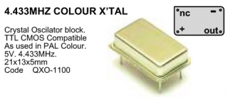
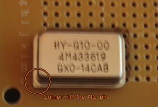
The image below is of the oscillator’s specs from the catalogue:
You’ll note that there are 4 pins and that it has rounded edges, the exception being the one labelled ‘NC’ or ‘not connected’ which was a straight edge – this is important so we know which pins require what in order to operate. The + pin requires 5v that we can draw anywhere from the board, and the – pin requires a ground connection that we can also grab from the board. The out pin is the bit that sends out the signal we need, and consequently is the pin we need to connect to the PCB point we’ve just cut. The nc pin isn’t connected, and we use the straight corner to work out how we wire everything up.
How you wire it is up to you – I threw it onto some veroboard and soldered to the underside of it, but looking back I probably didn’t need to. Since it can be a little squeezy inside the Mega Drive’s case, I wired everything so I could have it sitting in the space beside the PCB when I put the console back together, hence why I used long lengths of wire. There may be better options out there, but I figured that’d do for now.
With that out the way, let’s actually get to work.
Step 6: Wiring the oscillator, part 2
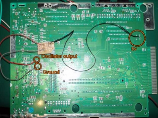
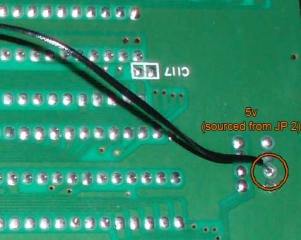
Okay, let’s do the deed. First up, wire the + and – points – I used the ground pin on the CXA-1144 (pin 1) to get my – bit, and tapped the 5v point over on where I set up my 50/60hz and language switches (see below for images – I’m pretty sure I tapped JP2 for it). I think the CXA-1145 has somewhere where you could tap 5v, but I was too lazy to work it out 😛 Grab some appropriate lengths of wire (as you can see below, I used reasonably long lengths for where I was going to let the oscillator sit), strip the ends, tin the tips and get to work on the + and – points.
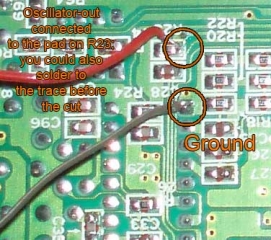
Next, we have to get the output from the new oscillator to feed into the CXA-1145 – you could either solder directly to the trace, or do the lazy method and solder to the pad the resistor is sitting on that runs along the trace (in the pics below, it’s the one to the right, or the one the trace runs off). Just don’t get too carried away and f&*% up the resistor, otherwise you’ll have to repair or replace it. The following images show how I hooked everything up:
Step 7: Finishing up
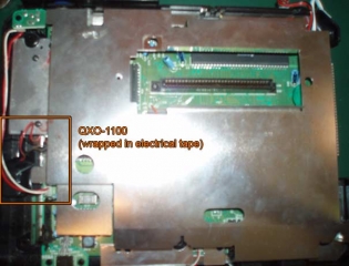
Well, that’s the bulk of it done. Use electrical tape on the connections to make sure you don’t stress the joins you’ve made, then wrap a layer of electrical tape around the chip to make sure nothing causes a short anywhere. Reassemble and don’t pull on those wires! I plonked mine near the headphone bits ’cause there was room there.
Step 8: Test it!
Test your Mega Drive and hopefully it works! I tested all my PAL, US and Japanese games and they worked fine. You’ll find that when you swap between 50/60hz there’s a lag of about 1-second before it gets the colour right, but that just be my display device. Otherwise, it’s all good. I’ve tested this in composite and s-video connections and had total success. In my testing, I have found the external oscillator does interfere with RGB output, so if you want to reverse it, desolder everything and bridge the gap you created when you cut the trace coming off pin 6 on the CXA-1145; alternatively, add a switch to go between the external oscillator and the original signal, which I’ve written a tutorial for if you need some help. I’ve posted previously about running this same Mega Drive through a RGB to component transcoder, and I had noise and colour issues; switching back to the original signal fixed all the issues, so if you want the most flexibility in your system, install the switch.
And that’s it! Good luck, and feel free to leave comments if you have any questions, or fire across an e-mail via the Contact page. If you want to view the lot, you can do so via the gallery.
