Reviewing… Story of Thor (Sega Mega Drive)
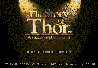
story-of-thor-title

I actually meant to get started on these reviews a while ago… better late than never!

My copy of Story of Thor and I go way back to 1994, when I was lucky enough to be given it for Christmas. I’d read the reviews from Sega-stalwart Sega Megazone and was just starting to get into anime (this interest would be fully realised as Robotech replayed over the summer holidays on Agro’s Cartoon Connection and when I saw 3×3 Eyes Part 2 at a friend’s place a few months later), so it seemed like a good combination. Ancient, and by extension Yuzo Koshiro (who rocked my gaming world with Streets of Rage 2 the year previous), helmed the game’s design and it gave me a chance to play a Zelda-like adventure game without having to swallow my pride and invest in a SNES (this would come 18 months later, but that’s another story). These are all very important points to a 12 year old boy you understand, so it’s important to irrationally preface this review accordingly.

I adored the game back in the day – it was an amazing feat for the humble Mega Drive and a fun game in its own right. When I went back to play it recently (“recently” being last year or the year before), I was still confident that the game would hold up well. Turns out I was right.

Visually I still think it’s fantastic – the Mega Drive’s colour palette is used sensibly (as it needs to be – only 64 of those colours can be on-screen simultaneously [or 183 in shadow/highlight mode – thanks Wikipedia]), sprites are large and well-animated (despite later enemies simply being palette-swaps) and there’s plenty of variety in the scenery. As a bonus, the game features a little sprite scaling when you fall down holes or gaping chasms. It’s all typical of Japanese game aesthetics of the era – clean, well-defined and charming with great attention to detail.

The fanboy wants to decry it the audio as an example of technical mastery for the system, and to a degree it is. The problem is that it hasn’t necessarily aged too well – Koshiro’s deft use of the Mega Drive’s audio chipset for the music is actually very good – it’s the garbled sampled audio that lets it down. Back when I was playing this on an old 51cm TV in my bedroom (complete with RF input and 80s faux-wood panelling contact over the MDF), I actually used to run the Mega Drive through my mini HiFi stereo and remember being impressed by the use of the stereo channels to simulate a surround-sound effect with the waterfalls in the palace. The effect’s still prolific, but the sample noise is a little rough on ears now. It was certainly ambitious, and was by no means unpleasant; today, it’s just a bit rough.

Another peculiarity is with the cartridge’s hardware itself and how it interacts with the Mega Drive. I normally run my Mega Drive games in 60hz, but the PAL Story of Thor cart is a bit of an anomaly with the way it handles the different refresh rates. When booted in 60hz it gives the usual region protection error, which isn’t uncommon – why it’s interesting is that when you try the usual trick to get around it (boot in 50hz, then swap to 60hz), the game slows to a halt and the image rolls. The only other games where I’ve seen the same thing happen are Streets of Rage 1 and 2, both of which also happen to be games by Ancient and involve Yuzo Koshiro. My only theory is that Koshiro is using either some unique hardware in the cart (I haven’t popped the cart open to have a look), or the oscillator that provides the refresh rate is tied to the way the game handles video timing, the Z80 audio CPU or other programmable variables. On the upside though, the PAL version of the game is surprisingly well-optimised for PAL TVs, including stretching the image so that it virtually covers the entire screen. I didn’t take notice of this back in the day (it wasn’t until the Saturn era that I became aware of PAL optimisation of games and the joys of 60hz), but it’s a nice touch looking back at it now.

It didn’t take me too long to plough through the game – my memory was surprisingly good and the game really isn’t too tough. There’s no excess padding with enough optional treasure hunting to get the balance just right (though I still didn’t manage to find all the hidden gems this time around!). I think it took up maybe… 5 or 6 hours? That’s a good time frame for me these days, as I’m time-poor given the realities of life typical of someone my age. Playing through games that last over 60 hours is a long slog when I only have a couple of hours each week (if that) to get in some gaming, so it meant Story of Thor was the perfect length to knock out in a couple of weekends.

I won’t assign a score for this one (or any other reviews for that matter), as I don’t think it’s necessary. What’s more important is the experience, and this one still delivers. The great news is that if you missed it back in the day, it’s available via the Wii’s Virtual Console for a cheap download, and M2’s work on the emulation on the Wii is amazing. It’s also on the Sega Mega Drive Collection (or Sonic’s Ultimate Genesis Collection for those in North America) on the PS3 and XB360, but the emulation isn’t anywhere near as precise as M2’s. Still, if that’s all you have access to, it’s worth a go. You even get a trophy/achievement for completing the first dungeon 🙂
Streets of Rage Remake hits v5.0 Final!

BomberGames’ epic Streets of Rage Remake project hit v5.0 Final earlier this month!

This is an amazing feat, and the game is work of art. As a huge fan of the Streets of Rage series, having spent countless hours playing through the originals (especially through SoR2 on Mania level!), this game is a masterful tribute to the series, combining new characters, accumulated specials, tweaks, remixes of old levels, and plays perfectly, just like on the Mega Drive.

All the details are on their announcement page – grab it and enjoy it (currently available for Windows/PC). The only way it could be better is if it was on PSN and XBLA and distributed by Sega, because the authors deserve wide exposure of this project and remuneration for their efforts. In turn, the game demands being played on a big screen on a console 🙂

Thanks to elvis over at Aussie Arcade for the heads-up!

Enjoy!

Adding a switch to the 60hz colour mod

Last year I wrote a guide to get colour video out of your Mega Drive via s-video, composite and RF cables, but I’ve noticed that since using the RGB to component transcoder, the colour was flickering on my CRT I play my Mega Drive on. I tested it on our flat panel TV, and sure enough there’s some extra noise in the picture when running the SMD with the external oscillator. So, I figured I’d make a switch to go between the original feed from the Mega Drive and the oscillator, which gives the best flexibility if ever I use the SMD via s-video or composite if I’m not hooking it up via RGB/component.

The theory is simple – grab a SPDT (single pole, double-throw) switch, wire the middle (output) pin to where we used to put the oscillator’s output, wire the oscillator to one of the remaining sides and grab the existing feed off the mainboard and wire that to the other. To help out, here’s what I did:

Equipment needed:

  • Remember to read this one in conjunction with the previous mod and have the oscillator ready to go!
  • Two wires of a length suitable for mounting the switch (remember you’ll only need two as the existing output wire off your oscillator will be fine for adding to the switch, unless you need to lengthen it, then you should replace it)
  • SPDT (single pole, double throw) switch
  • Solder, soldering iron, screw driver and drill/drill bits for mounting the switch

Disclaimer

You mod your machine at your own risk. Myself nor anyone else is responsible for YOU modding YOUR Mega Drive/Genesis. If your machine doesn’t work as a result of this, don’t blame me – you do this mod at your own risk.

Step one:

Obviously, discharge and disassemble your Mega Drive and remove the mainboard and have it facing up. Be careful you don’t damage the wires hooking the oscillator you fitted from the previous tutorial.

Step two:

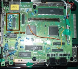
As per the previous mod, here’s the input signal being fed from the external oscillator into the CXA1145 IC. We’ll need to remove this to replace it with the switch’s output so we can select between the original and oscillated frequencies.

Step three:

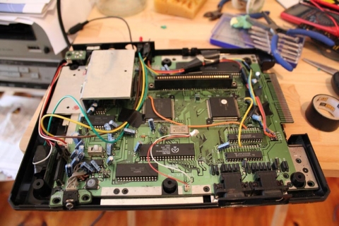
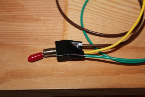
Here we have a SPDT (single pole, double throw) switch wired up and ready to go. The middle (yellow) wire goes to the CXA1145 IC’s input, which is where we used to send the oscillator if you followed the previous mod; the green wire is from the external oscillator, and; the brown wire will take the original feed from the Mega Drive’s mainboard for RGB compatibility.

Step four:

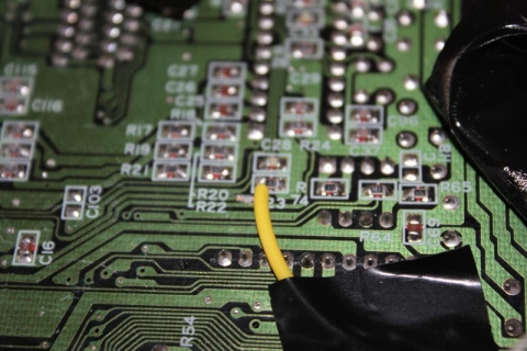
This shows the middle (yellow) wire from the switch wired to where we used to put the oscillator. It functions as the output from the switch’s two sources.

Step five:

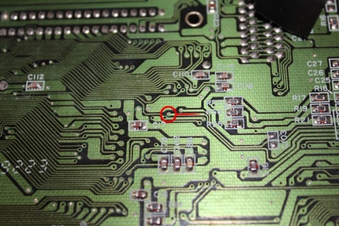
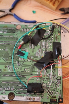
I’ve highlighted a point on the underside of the mainboard where you can easily solder a wire to connect to carry the Mega Drive’s original frequency to give RGB compatibility.

Step six:

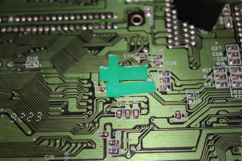
To ensure I only wire the correct signal, I use some electrical tape to isolate the solder point.

Step seven:

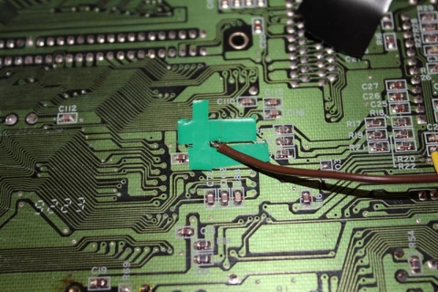
Tin the tip, heat some solder and attach one of the wires from your switch’s input poles to the point. I’ve used the brown wire.

Step eight:

If you haven’t done so already, grab the output from the oscillator and wire it to the other side of the switch. If the wire isn’t long enough to reach to where the switch will be mounted, remove it and use another wire – it’s best to avoid joining wires together part-way along the oscillator’s input to ensure the signal remains strong and steady.

Step nine:

And that’s all there is to it – use the output from the oscillator (green) and attach that to the other side of the switch, secure your connections with electrical tape, and get ready to assemble. For those interested, the black wire at the top of the mainboard in this pic is a hardwired composite socket I built so that I could use standard AV cables with my Mega Drive.

Step ten:

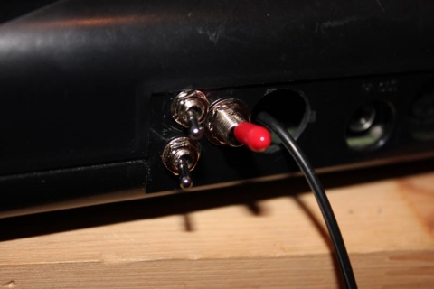
I wanted to keep everything on the back of the unit, but placed in a way that would allow for the Power Base Converter to still be hooked up, so I installed the switch next to the 60/60hz and JP/Eng language switches which are next to the AV socket, where the Ext. socket would be if I had an earlier-model Mega Drive 1.

All in – would be great if I’d lined up those holes a little nicer though! Once I had the switch installed, I found I was no longer getting any issues with my Mega Drive when running it in RGB via the transcoder, so if you intend to run the machine in RGB at some stage, fit the switch!

PAL Sega Mega Drive colour correction – 60hz in full colour in RF, composite and S-Video!

Update (7 April, 2011): I’ve noticed this method introduces noise in the RGB channels when playing games via RGB or via a transcoder. Therefore I recommend you add a switch to go between the original signal and the oscillator for best results. A tutorial to do this can be found here.

A few years back, with the help of the regulars at the NFG forums/GameSX (in particular, Viletim! was instrumental in helping me with this), I was able to put together a relatively simple method for getting 60hz in full colour out of a PAL Mega Drive when output via RF, composite and S-Video, and a method that still kept the full colour signal even if switched back to 50hz on the fly. Apologies in advance for some of the pics, but I hope other modders find this one useful. The other essential resource for getting this happening was Charles McDonald’s Home Page, so huge thanks out there as well.

Equipment needed:

  • 4.43mhz crystal oscillator (WES Component # QXO-1100, source [Australia])
  • Thin-gauge wire
  • Soldering iron (15 or 25 watt – I use the latter, but 15w ones are better I’m told)
  • Solder and desoldering wick (if you stuff up)
  • Stanley knife or something sharp to cut PCB traces
  • Screwdriver (d’uh!)

Disclaimer

You mod your machine at your own risk. Myself nor anyone else is responsible for YOU modding YOUR Mega Drive/Genesis. If your machine doesn’t work as a result of this, don’t blame me – you do this mod at your own risk.

Intro

Throwing a 50/60hz switch is easy to do on a Mega Drive – for PAL gamers, the problem is to get it to output the 60hz signal in colour. Providing you have a telly that can accept RGB via SCART, this is a non-issue – the RGB feed comes out great regardless of whether its in 50hz or 60hz. Should you have a 32X, you’re also set – the a/v-out on the 32X cleans up the 60hz colour issue, though apparently some early model Mega Drives still have issues despite this.

So, if like myself and plenty of others you don’t have a SCART socket on your telly or a 32X, this mod will show you how to fix up this arse of a fault in your PAL Mega Drive and get it to output 60hz as a proper PAL60 signal, whether it be via crappy composite leads or a custom-built s-video connection. Props out to viletim! from the NFG Games forums who came up with the solution btw – we in the community owe this one to him! Note this was all done on an original model PAL Mega Drive, not model 2 or 3 or what-not; your console may differ from mine, so you mod your machine at your own peril.

Step one: Disassemble Mega Drive

This one’s pretty easy so I won’t go into it – disassemble the whole lot, including the heatsink and everything. We want to be able to take the PCB (printed circuit board, or the board that is the guts of the Mega Drive) entirely out off the case to get to the underside of the PCB itself. If you know your way around the Mega Drive, you could probably skip taking the heatsink off the board itself if you know where the CXA-1145 chip is; otherwise, remove it.

Step two: locating the chip

The aim of this mod is to feed a new signal onto pin 6 of the Mega Drive’s CXA-1145 chip to get it to generate a colour picture when it’s running in 60hz. Obviously to do this we’ll need to find the chip. The CXA-1145 (or the Irony Chip as I call it – “It’s a Sony”) is located on the top left-hand side of the PCB underneath the poxy RF mod we all used in the 90s owing to our crap-tacular tellies. See the image below for a general guide:

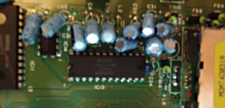
Or for a dodgy close-up view, here’s this:

Our victim will be pin 6 of the CXA-1145, which is the oscillator input. Apparently anyway. Viletim! said it was, and my crap understanding of schematics reckons that’s what its called, so we’ll call it that. You could also name the pin the “Mr Bob” pin or “I wish I were as cool as Sauceman” pin for all I care (“Kloppy is a champ” pin is another), as long as you use pin 6, it’s all good. To work out which is pin 6, count from the bottom-right of the chip if you’re looking at it normally, or in the above image, the bottom left-hand side (the one with a little ‘1’ printed on the PCB) and count up six pins… or just use the above image as a guide and count to the right. It’s all good.

Step three: Cutting the trace

Now we’ve located the chip and the pin, we need to turn the board over so we can attack it with a stanley knife or equivalent cutting device (I’ve heard of x-acto knives or somesort being talked about in the past – whatever, as long as you can use it to cut a trace on the PCB). You could use pin 1 as a guide and count up then follow the traces from pin 6 through a capacitor and a resistor to get to the point we need, but thanks to the power of the intarweb [sic] and some schematics available online, we can use the references to the capacitors and resistors to work out what we’re supposed to cut.

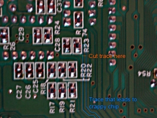
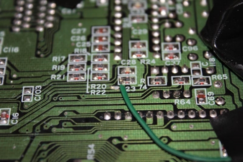
You’ll need to look for ‘C28’ and ‘R23’ – see below:

Now, the astute observer will notice that there is a thin trace that runs off the resistor and continues along its merry path to the 315-5313 IC8. What we need to do is cut this trace AFTER its followed the resistor – see below for an example:

And for your reference, here’s what I did:

Make sure you do this carefully and DO NOT cut any of the other traces nearby. Good lighting and a steady hand makes a really big difference here – be patient cut the trace all the way through. You’ll know you’ve severed it when you can see the green trace all gone and the core of the circuit board is visible; you know, the light brown stuff. If you don’t cut it all the way through, the mod won’t work correctly. If you accidently cut the wrong trace or damage a nearby one, make sure you bridge it – GameSX has some good guides to this, so visit their website for more info.

Step 5: Wiring the oscillator, part 1

Okay, before we get into soldering to the PCB, let’s get our oscillator ready to go. All this is based on the assumption you’re using the WES component # QXO-1100 that I used; I’m assuming you could substitute it for something similar, but you do that at your own peril. I’m just following what was suggested to me.

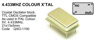
The image below is of the oscillator’s specs from the catalogue:

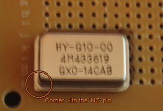
You’ll note that there are 4 pins and that it has rounded edges, the exception being the one labelled ‘NC’ or ‘not connected’ which was a straight edge – this is important so we know which pins require what in order to operate. The + pin requires 5v that we can draw anywhere from the board, and the – pin requires a ground connection that we can also grab from the board. The out pin is the bit that sends out the signal we need, and consequently is the pin we need to connect to the PCB point we’ve just cut. The nc pin isn’t connected, and we use the straight corner to work out how we wire everything up.

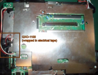
How you wire it is up to you – I threw it onto some veroboard and soldered to the underside of it, but looking back I probably didn’t need to. Since it can be a little squeezy inside the Mega Drive’s case, I wired everything so I could have it sitting in the space beside the PCB when I put the console back together, hence why I used long lengths of wire. There may be better options out there, but I figured that’d do for now.

With that out the way, let’s actually get to work.

Step 6: Wiring the oscillator, part 2

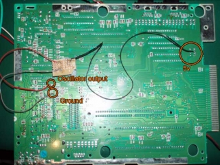
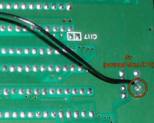
Okay, let’s do the deed. First up, wire the + and – points – I used the ground pin on the CXA-1144 (pin 1) to get my – bit, and tapped the 5v point over on where I set up my 50/60hz and language switches (see below for images – I’m pretty sure I tapped JP2 for it). I think the CXA-1145 has somewhere where you could tap 5v, but I was too lazy to work it out 😛 Grab some appropriate lengths of wire (as you can see below, I used reasonably long lengths for where I was going to let the oscillator sit), strip the ends, tin the tips and get to work on the + and – points.

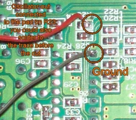
Next, we have to get the output from the new oscillator to feed into the CXA-1145 – you could either solder directly to the trace, or do the lazy method and solder to the pad the resistor is sitting on that runs along the trace (in the pics below, it’s the one to the right, or the one the trace runs off). Just don’t get too carried away and f&*% up the resistor, otherwise you’ll have to repair or replace it. The following images show how I hooked everything up:


Step 7: Finishing up

Well, that’s the bulk of it done. Use electrical tape on the connections to make sure you don’t stress the joins you’ve made, then wrap a layer of electrical tape around the chip to make sure nothing causes a short anywhere. Reassemble and don’t pull on those wires! I plonked mine near the headphone bits ’cause there was room there.

Step 8: Test it!

Test your Mega Drive and hopefully it works! I tested all my PAL, US and Japanese games and they worked fine. You’ll find that when you swap between 50/60hz there’s a lag of about 1-second before it gets the colour right, but that just be my display device. Otherwise, it’s all good. I’ve tested this in composite and s-video connections and had total success. In my testing, I have found the external oscillator does interfere with RGB output, so if you want to reverse it, desolder everything and bridge the gap you created when you cut the trace coming off pin 6 on the CXA-1145; alternatively, add a switch to go between the external oscillator and the original signal, which I’ve written a tutorial for if you need some help. I’ve posted previously about running this same Mega Drive through a RGB to component transcoder, and I had noise and colour issues; switching back to the original signal fixed all the issues, so if you want the most flexibility in your system, install the switch.

And that’s it! Good luck, and feel free to leave comments if you have any questions, or fire across an e-mail via the Contact page. If you want to view the lot, you can do so via the gallery.

Getting component video out of a Sega Mega Drive (works for other RGB signals as well!)

Update: Some HDTVs aren’t compatible with low-resolution (240p) video signals via component video, something I’ve discussed in more depth in a recent post.

This topic has come up a few times on one of the forums I frequent so I figured it couldn’t hurt to post a quick how-to if anyone else is interested in a no-solder solution for getting component video out of a Sega Mega Drive, something that’s particularly handy if you have display devices that can’t take RGB via a SCART cable (like yours truly!).

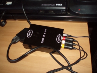
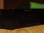
The concept’s simple – grab a RGB signal out of the Mega Drive, run it through a transcoder, display on your TV. The trick was finding a box that could do it, as a simple input converter won’t do the trick, you need to transcode the signal on the fly for it to work. Previously this has been a bit pricey to do, but with eBay and other stores flooded with a stack of RGB to component (or YUV if you prefer that acronym instead) converters, it’s not too difficult to track one down, especially following GameSX’s excellent wiki entry on the CSY-2100 chipset.

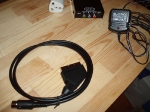
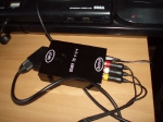
So, on with the simple tute – grab a decent RGB SCART cable (I got mine from an eBay seller in the UK called pcenginesales, excellent product, price and service), ensuring the cable’s carrying RGB and not just composite video, a transcoder (mine came with a UK 12v AC adapter, so I just added a power point converter to it since we run 240v locally as well), three RCA cables (colour coded if it helps, I had a spare set of composite AV cables that did the job fine) and an extra spot on your power board for the AC adapter.

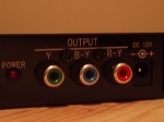
As for method, dead easy again – plug the SCART cable into the rear of the Mega Drive, fire the other end into the SCART input on the transcoder, connect your RCA cables into the transcoder’s YUV outputs, then run them to your TV/AV receiver/etc.

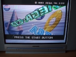
The end result is an extremely clean and beautiful picture that gives an indication of what a true RGB signal can look like as a component video output. I’ve posted some comparison shots below that go some way to demonstrating the improvement, but you really need to see it to believe it.

And as an added bonus, flicking the Mega Drive into 60hz won’t affect the colour output, as the transcoder’s grabbing the signal from the RGB outputs on the CXA1145 encoder and not the signal from the composite output. While you can go to town on the Mega Drive’s internals to get colour output on RF/composite/s-video output (I’ll add a tute on how to do that in the not too distant future), this is a simple no-solder solution that gives great video quality. It’ll of course cost a bit more than doing the internal mod, but I love the results.

I did notice that at times the colour flickered a little on my unit, but I had a hard-wired composite connection I added to the back of my Mega Drive, and once I hooked that into my switchbox for the hell of it, the flickering via the component video stopped. Not sure the issue – could be noise from the transcoder or switchbox, weird pulses in the Mega Drive due to the mods I added to get colour in 60hz via composite/RF/s-video, might be something else entirely. Probably won’t affect you, but there you go.

For the visual tour, see the gallery below!