Virtua Fighter 2 (Model 2) and Virtua Fighter 3 (Model 3) booting and power supply (PSU) problems

I’ve posted this in a few forums, so thought I’d track it on my blog as well. The following’s a slightly edited version of my post 🙂

A few months back I snapped up VF2 and VF3 from someone interstate, and have been having some troubles with them, and I’m not sure if it’s me, the boards, or maybe a combination of both!

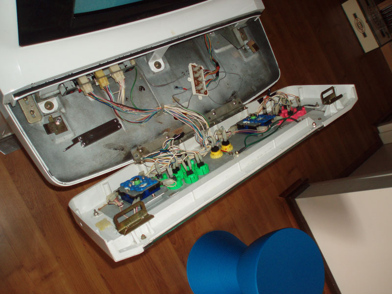
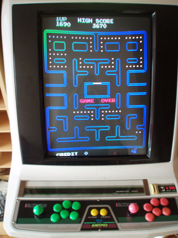
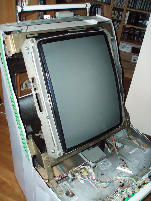
Now, before I go on I’ll clarify my setup – Astro City cab with a 15k/24k chassis (Pentranic, previous owner slapped in a generic 15k chassis that blew up, so I replaced with a Pentranic), bog-standard Peter Chou 15A PSU, 3.3v Wei-Ya PSU, cab is JAMMA-ready. To connect the Model 2 and Model 3 boards into my JAMMA setup, I’m using one of these (Model 2) and one of these (Model 3).

In order to boost the 5v and GND lines on the main PSU, I’ve also increased the amount of wires coming between the PSU and the JAMMA connector as I wasn’t getting solid +5v due to some flimsy wiring. After beefing up both lines, I’m getting much better performance across all my PCBs (CPS-I, Neo Geo, CPS-II, System 11 and a few others).

I’ll start with VF2 – I’ll put the chassis into 24k mode, roll the PSU back, connect VF2 and get the voltage to 5v (maybe 0.05v over). On the PCB, the red LED 11 is lighted up, and I’m getting like a garbled green test pattern thing on the screen. I’ve pulled the PCBs apart and put them back together again, checked to make everything’s in there nice and tight and checked for physical problems on the boards, everything checked out, no change. To test things a bit further, I removed the top ROM PCB, leaving the bottom two boards (since it’s a Model 2A system, it’s a platter of three boards) and rebooted – same problem, LED 11 is lit up, I think I saw a couple of red LEDs on the bottom board near the filter board light up, and the garbled screen. Turned off, put the ROM board back on, the LEDs on the bottom board are fine, but the red LED 11 in the middle board is still lit up. Garbled test pattern remains.

With VF3, it’s a bit more tricky, and I have a feeling it’s my PSU that’s to blame here, as well as some of my wiring before I beefed up the 5v and GND lines. With VF3 when I first tried booting it a month or two back, the 3.3v PSU worked a treat, but the old Peter Chou would crash out immediately – the red light to indicate it was on would light up, then immediately drop out and there’d be no power on the JAMMA adapter when I tested it with my multimeter. I figured my PSU might have been on the way out, so got a new standard arcade PSU (a 16A Min Dong), connected it up and had success… or at least I thought I did. I measured at the JAMMA adapter and it wasn’t getting to even +2v on the +5v line; I cranked it, barely got to +2v and the JAMMA adapter was getting really hot. Next thing I knew, it smelt like the PSU was overheating and the little light indicating it was on turned off. The new PSU went and died on me 😛 Disappointed, I reconnected the old Peter Chou PSU. I noticed a couple of red LED lights come on when I power up the Model 3 off the Peter Chou (even though ti conks out) and the 3.3v Wei-Ya (which I’m going to take as meaning the Wei Ya is working fine, since it doesn’t conk out), if that helps. Another thing I noticed is that how much success I have before the Peter Chou PSU gives up depends on the amount of +5v/GND connections – I can have the 5v and GND connections on, say, JST CN13, and it won’t kill the PSU, but if I hook up JST CN14 as well, the PSU dies. Does this help?

I was talking a few other people with more experience than I have with arcade cabs, and they mentioned that the fact the JAMMA adapter was heating up indicated there wasn’t enough copper between the PSU and the JAMMA adapter on the +5v and possibly the GND connection as well, and suggested beefing up the wiring to fix that part. I’ve done that and am getting better results when playing the rest of my games, and when I tried loading VF2 or VF3 with the beefed up wiring, VF2 still gave that garbled green test pattern screen thingie (red LED 11 still on), and VF3 still died off. They also mentioned the red LEDs might be indicating a fault with the board or power supply.

I’m a bit stumped with what I can do to fix up these issues – I’m a huge VF fan, and these two games were part of the reason I wanted to get my own arcade cab. I know there are some very clued up Model 2 and Model 3 people on these forums, but couldn’t find anything that coped with these problems. I’m not sure if it’s a PCB, PSU or even jumper settings issue that’s affecting my PCBs. Some other people I’ve spoken to who run Model 2 boards have done it consistently off standard arcade PSUs for years, but they emphasise that you need to ensure your +5v and GND connections need to be extremely strong in order to do so.

Changing the arcade cab’s joysticks – 4-way, 8-way, 2-way

So I’d read quite a while ago about changing the gate or plate on your arcade cab’s joysticks and never really “got” it… I mean, I only remember using standard 8-way joysticks when gaming, but I think I’ve finally worked it all out 🙂

It all happened as a result of getting the 48-in-1 installed in the machine – when Wifey and I sat down for some retro gamage, we found that in some cases it just wasn’t controlling that well… Pac-man in particular was problematic! So afterwards I popped open the control panel to see how it worked:

Changing the Sanwa JLF standard gate (rectangle), part 1

So, by default my cab was setup for 8-way control (i.e. what most modern games use for control), which for the standard rectangle gate on the Sanwa is in the middle:

Changing the Sanwa JLF standard gate (rectangle), part 3

The shape in the rectangle controls the freedom of movement the base of the joystick shaft has when it sits in the control panel. So, by changing the configuration of the rectangle gate, you can control the joystick’s degree of movement, restricting it to 8-way, 4-way or 2-way (horizontally or vertically).

To get started, remove the screws holding it in place:

Changing the Sanwa JLF standard gate (rectangle), part 4

From here, you’ve got the rectangle plate itself:

Changing the Sanwa JLF standard gate (rectangle), part 5

On the left is the 4-way template, in the middle is the 8-way template, and on the far right is the 2-way template, which you can set for vertical or horizontal. I can’t think of too many vertical 2-way controlled games you’d play with a joystick (I mean, Pong can be setup for vertical play, but you’d normally use a spinner instead of joysticks), but still, I’ll show how you set it up 🙂

4-way:

Changing the Sanwa JLF standard gate (rectangle), part 6

2-way, vertical:

Changing the Sanwa JLF standard gate (rectangle), part 7

I thought I took a snap of it in the horizontal position, but mustn’t have… go me 😛 Anywho, you pretty much grab the rectangle as per the above image, and swing it around 90° clockwise, then screw it in again.

Anywho, I’ve currently got the two Sanwa sticks locked into 4-way mode at the moment, which means that, in theory, I should now do much better at Pac-man, right?

Changing the Sanwa JLF standard gate (rectangle), part 9

Oh well, I’d better get back to practicing 😉

… because I am so, so bad at that game!!!!!!

Anywho, there are a handful of extra pics on page two of the Arcade Stuff – Cabinets gallery, so feel free to check it out (and remember, there’s full blah-blah commentary when you click on any of the thumbnails).

Rotating the monitor on my Sega Astro City

Disassembling the Astro part 3...

Finally got around to rotating the monitor on my cabinet on the weekend – my father-in-law was staying with us for a few days, and since he was keen to give Galaxian and Galaga a go (and those are on the 48-in-1 I picked up a while ago, along with plenty of other classics!), it wasn’t too hard to convince him to give me a hand rotating the monitor since I’m not strong enough to do it on my own 😉

Anywho, it wasn’t too tricky – simply take off the shroud by flipping open the control panel, remove the screws holding the plastic housing down, unhook the connection to the speakers (mine was easy to disconnect with a handy molex connector), remove the screws and two plates on the back of the cab (the top panel hides the fluro tube and the speakers, the next one down hides the access to the monitor chassis), then slowly lift the shroud off. Next up, I disconnected the cabling between the RGB lines from the JAMMA connector from the chassis, then tested the AC line to the chassis (plenty of give) and removed the screw that were bolting the cab to the frame. Next up, lift and turn the monitor clockwise or anti-clockwise (erm, I can’t remember which… 😉 ) and re-sit it on the bolts and wind them up again. If you’d like me and the image is upside down, don’t panic – I unplugged the yoke connector on its existing socket on the chassis and plugged it into the other one – fixed it right up (though don’t forget to disconnect the power between these tests!!). Once all that was done and it survived the smoking tests, I wound the voltage on the PSU back to +5v flat without a JAMMA board connected, plugged in the 48-in-1, wound it up to +5v on the mark, tested it up, and bam, worked fine! Mind, the monitor needs a really thorough degaussing, so I’ve added a degaussing wand to my “to-get” list to fix that up.

Disassembling the Astro part 7...

Anywho, on Sunday I jumped in and started messing with the DIP switches, and have it all nicely configured. Also started messing around with the gate on my Sanwa sticks, but that’s something to discuss in another post 😀

The important bit, though, is that it was awesome fun to play through the classic games 😀 My top pick at this stage is either Space Invaders or Shao-Lin’s Road 😀 😀 😀

If you want more pictures of the cabinet and rotating it, you can view them in the new arcade stuff – cabinets gallery.